Showing posts with label Rotary Tool. Show all posts

Sunday, April 25, 2010

Fuel Pressure Regulator

I'll let the pictures tell the story this time ...

Before: 1971 Volvo 1800E Fuel Pressure Regulator - Before After: 1971 Volvo 1800E Fuel Pressure Regulator - After

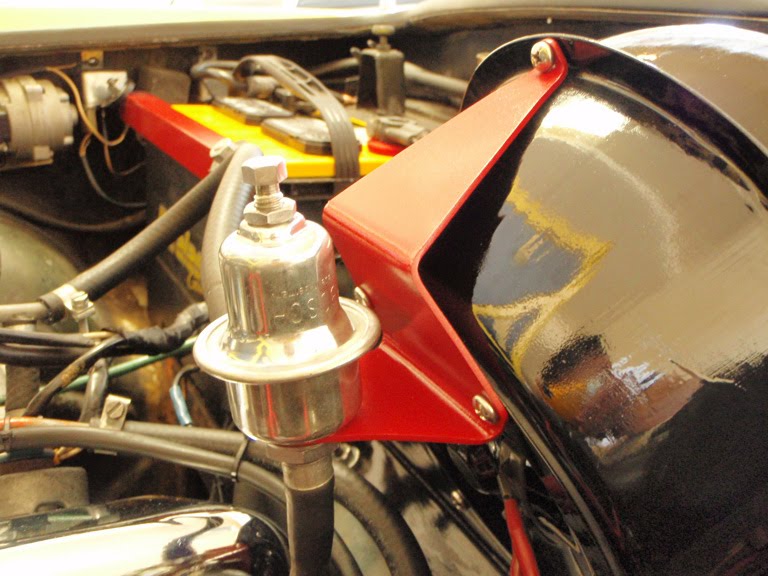
Fuel pressure regulator shown below was restored using a polishing wheel attachment on the Dremel rotary tool and Mothers Billet Metal Polish.

Before: Volvo 1800E Fuel Pressure Regulator - Before After: Volvo 1800E Fuel Pressure Regulator - After

Mounting bracket for fuel pressure regulator:

Before: Mounting Bracket - Before During: Mounting Bracket - During
After: Mounting Bracket - After Mothers Billet Metal Polish: Mothers Billet Metal Polish

The following photos are of the engine bay when I first got the Volvo compared to what it looks like to date:

Before: Volvo 1800E Engine Bay - Before After: Volvo 1800E Engine Bay - After
Volvo 1800E Engine Bay - BeforeVolvo 1800E Engine Bay - After

Sunday, March 7, 2010

Got It ... Kinda!

I managed to get the engine running way past the 7 minute mark after making adjustments to the air/fuel mixture. It's not pretty ... the engine revs higher than I'd like it to at idle, but that should keep it from stalling when I drive it to the shop. The first thing I did after the static timing, was to invest in a fuel pressure gauge. The fuel pressure was indeed at the recommended 30 psi. Next, I adjusted the throttle butterfly located in the mouth of the intake manifold. This was done via the throttle adjustment screw pictured below. The various instructions call for a 1/4 or 1/2 turn of this screw from the point of contact with the throttle valve spindle. I did mine at 1/2 turn. By the way, I had to use a dental mirror to get a visual of when the screw was making contact with the throttle valve spindle. The purpose is for this screw to hold the throttle slightly open as it should never be completely closed. I found that mine was originally opened more than it needed to be as if someone used this to adjust the idle instead of the idle adjustment screw located below the mouth of the intake manifold. The second photo below shows the throttle adjustment screw after the adjustments have been made. Having messed with throttle butterfly, the next procedure was to reset the position of the throttle switch to accomodate the new setting.

Throttle Adjustment Screw: Throttle Adjustment Screw Close-Up: Throttle Adjustment Screw

Next, was the idle adjustment screw - I removed it completely from the manifold and cleaned it up with electronic contact spray. Here's how it looks like pictured below. I also sprayed a whole bunch of electronic contact cleaner down the hole indicated by the red arrow in the next photo below. This is where air for idle gets through and the volume of air is restricted by the idle adjustment screw. Needless to say, a tsunami of black stuff came out of that hole that could be restricting air flow.

Idle Adjustment Screw: Idle Adjustment Screw Throttle Butterfly: Throttle Butterfly

I also figured out what that knob was on the side of the ECU. I originally thought it was some sort of fuse (red arrow in the photo below), but it's the idle enrichment knob. It controls the richness or leaness of the mixture, but only at idle. Clockwise is richer, counter clockwise is leaner. It increments in "clicks". Once all that stuff above was dialed-in, tuning the idle air/fuel mixture was a matter of adjusting the idle screw and messing with the idle enrichment knob on the ECU.

Idle Enrichment Knob on ECUSince I don't own any instruments like a CO meter, or revolution counter, adjustment of the idle and air/fuel mixture was done "by ear" and the use of a caged canary next to the exhaust pipe. Alright ... it was way less low-tech than that! Using my own body as an indicator, the more nauseous I got and the more burning and watering of the eyes from the exhaust fumes - the richer the mixture. So I adjusted the idle screw and leaned out the mixture via the idle enrichment knob on the ECU accordingly until the feeling of wanting to throw up went away.

It was tricky dialing in the right combination of idle air flow and mixture richness/leaness to arrive at a compromise that'll work for now. All this has to be done with the engined warmed-up by the way. Lot's of trial-and-error and measuring engine "run time" with a stop watch to see if it's running past the 7 minute mark. My neighbors hate me now I'm sure of it, and I think I might have also single-handedly depreciated the real estate values in my neighborhood while prospects were attending open houses this weekend.

Before: After:

In the midst of all the adjustments, I also managed to sneak in some "rotary tool" time and went to town on that thing that secures the throttle cable to the manifold. I don't know what it's called, but the before-and-after pictures are above. In the end, I took the Volvo out for a spin around the neighborhood for various lengths of time, stopping at every intersection to see if the idle drops and the engine stalls. Aside from sounding like I have a V8 under the hood, there were no problems at all during my test drive. It is only after each test drive, when I'm pulling into the drive way, the idle drops and I have to tap the gas pedal to keep it from stalling! I drove it for 20 minutes one time, and it almost stalls 10 feet from the driveway. Drove it for more than 30 minutes another time (all the while stopping-and-going to try to get it to stall - it didn't), and it does the same thing 10 feet from the driveway as I was returning from the test drive. The street is flat too, so I know it's not the incline in my driveway that's causing stuff to shake up in the gas tank and possibly leading to fuel restriction. Can you believe this?!!! It's like the Volvo is trying to tell me that it doesn't want to be in the garage ... it want's to be DRIVEN! Well then ... I hope it won't embarass me on the drive to my mechanic's shop.

Monday, February 15, 2010

Throttle Position Switch

Following-up on a lead that I read somewhere on the forums regarding a dirty Throttle Position Switch (TPS) leading to erratic idling and engine stalling, I decided to give my TPS a thorough cleaning to see if that solves my engine problem ... or at least eliminates the TPS as the source of the problem. At present, I'm not entirely sure of the mechanics of how it might contribute to the issues I'm having as I read about it late at night while I was half asleep, but detaching the plastic cover revealed some black scuff marks on the contacts as indicated by the red arrow in the first photo below. This was easily rubbed out with electronic contact cleaner and q-tips, followed by light dusting of the entire unit with the Dremel rotary tool with the soft bristle brush attachment.

Before: After:

Nope - didn't change a thing. Engine still starts up and idles fine until it warms-up, then it starts idling erratically and stalls. I didn't think it would work anyway since the symptoms are obviously heat related. I have my money on the coolant temperature sensor for now as the Fuel Injection Control Unit relies heavily on this very sensitive piece of equipment. Testing the resistance of the temperature sensor with a cold engine yielded a reading of 3000 ohms (within specs at 65 degrees room temperature). I took another reading when the engine was hot (after letting it run for a while until it stalled), and I got 0 ohms. I'm not entirely sure if its supposed to go all the way down to 0 since none of the resistance charts that I've seen for the temp sensor bother to show that range. Based on those readings, it does seem that the temp sensor is working like it ought to. However, it didn't occur to me while I was performing the test to see how quickly it reached 0 ohms. I'll do that this weekend, starting and stopping the engine at 1 minute intervals and then taking resistance measurements to see if I get a range of values.

Sunday, January 24, 2010

Coil Not Getting Full 12V

Volvo 1800E Coil Wiring

When I installed the Pertronix Flame-Thrower ignition coil last weekend, I discovered that the coil was not receiving the full 12 volts required for optimum performance (I was reading only 10V on my volt-meter). The installation literature suggests that there is a resistor somewhere in the circuit that needs to be removed in order to get the full 12 volts. Well, first of all I don't even know what a resistor looks like, and a close inspection of the wiring schematic didn't reveal any resistors leading to the positive terminal of the coil. Here's a link to a nice wiring diagram in PDF format that you can zoom in on for a 1972 1800E (should be the same for a 1971 1800E ... I think?!!) Of course, me reading an electrical schematic is like a 3 year old reading the Wall Street Journal.

So, either there really is a resistor, or there's a voltage bleed somewhere somewhere in the circuit leading to the positive terminal of the coil. From what I can tell, the 2 brown wires feeding into the positive terminal of the coil are from the main fuel injection relay and from the horn relay via fuse #6 in the fusebox. In this 1st photo, the twin brown wires are shown connected to the positive (top) terminal of the coil. Red wire from negative terminal of coil goes to the tach. Figuring out the wire colors was a task all by itself since all my wires are black ... they're either spray-painted black by some previous owner or black from years of grease and dirt fusing to the wire jackets! Only with some 1-on-1 time with the rotary tool did I manage to coax the wires to reveal their "true colors".

Fuel Injection Relay - Before: Volvo 1800E Main Fuel Injection Relay - Before Fuel Injection Relay - After: Volvo 1800E Main Fuel Injection Relay - After

A volt-meter test on the battery showed a full 12 volts, so I decided to trace the source of the voltage drop by removing the main fuel injection relay, cleaning up all connections with the rotary tool and some electronic contact cleaner, reattaching all connections, and ensure proper grounding. The only thing missing is I need to get my hands on some anti-corrosive zinc paste that I read about in this excellent article about electrical connections in our old Volvos. This guy is almost fanatical about the stuff, needless to say, I found new religion. I also extended the session with the rotary tool to include the restoration of the relay housing pictured in the before-and-after photos above. First, a rotary paper sanding bit was used to remove surface impurities, followed by the stainless steel rotary brush to get that brushed steel finish.

Of course, after hooking everything back up and in my haste to test the voltage, I mistakenly set the multi-meter to test resistance and completely fried the unit! I probably just blew the fuse in it. In any case, I wouldn't know the results of my efforts until I have the fuse replaced and my multi-meter working again ... story of my life.

Saturday, December 12, 2009

Hood Support

Spent a week slowly chipping away at the hood support with the Dremel rotary tool, a half-hour each night grinding, deburring, and polishing until finally all the dirt and discoloration were gone. I've reattached it to the Volvo today, which means the hood can now stay open, thus paving the way for the rest of the stuff to be placed back into the engine bay.

Before: Volvo 1800 Hood Support - Before After: Volvo P1800 Hood Support - After

Saturday, November 28, 2009

Air Intake Grille

I've been spending a lot of the Thanksgiving weekend painting, priming, eating turkey, watching paint dry, sanding, repeat ... none of it worth any pictures. I thought I had the whole weekend planned out - sanding primer down on some components and spray painting a fresh coat of paint, when a neighbor caught me in the process of sanding and said "You know ... you'll get a much smoother surface by wet sanding that." Huh? Wet sanding? So now I'm back to square one, repriming, and googling "wet sanding." Well, at least I have these photos to put up. Somewhere between the 4th helping of turkey and watching paint dry, I busted out the Dremel rotary tool and went to town on the clips and fasteners for the air intake grille. Both the air intake baffle which has a fresh coat of paint from last week and the polished grille are now back in the Volvo.

Air Intake Baffle: Volvo P1800 Air Intake Baffle Air Intake Grille: Volvo P1800 Air Intake Grille

Sunday, November 22, 2009

Heater Control Valve & Heater Fan Motor

I finally have the heater control valve and the heater fan motor sorted out. I've been working on these two components for weeks, a half-hour here, a half-hour there - just whenever I have the time. The foam gasket had melted all over the heater control valve causing a tremendous mess, and the pipes had been painted over. Quick work with the Dremel rotary tool revealed a pleasant surprise - copper pipes on the heater control valve! All the moving parts and internals were also cleaned up using electronic contact cleaner and Q-tips. Why the electronic contact cleaner? There are no electrical parts in the heater control valve, but the electronic contact cleaner was all I had so I decided to give it a try. It works great, especially in dissolving the melted foam away. All it needs now is some machine oil on the moving parts and it's good to go.

Heater Control Valve - Before: Heater Control Valve - Before Heater Control Valve - After: Heater Control Valve - After

A few weeks ago, while disassembling the heater core, I discovered that the capillary sensor cable from the heater control valve was broken. Turns out that this heater control valve must have been a replacement unit at some point in the Volvo's life as it has a capillary sensor that is still in tact. The first photo above shows this capillary sensor cable with the "bulb" on the end. The theory is, the capillary cable has ether in it which expands as it exposed to heat, and thereby toggling the valves to open or close slightly to regulate the flow of heated coolant through the heater core. Well ... I've read some feedback on the 1800list that this whole contraption never really worked that well anyway in "automatically" regulating heat, and you're better off just regulating it manually via the heater control cables. I decided to put this to the test and submerged the capillary sensor cable into a pot of water over the stove and slowly heating the water to a boil. Yup - doesn't work at all! Don't bother routing it back inside the heater box where it originally belongs. Just roll the capillary sensor cable up into a neat coil, and tuck it out of sight when replacing or reinstalling the heater control valve. You'll pass out from heat exposure long before the heater control valve decides to work auomatically - case closed!

Heater Fan Motor - Before: Heater Fan Motor - Before Heater Fan Motor - After: Heater Fan Motor - After

The heater fan motor - now this thing was a piece of work! Everything had siezed up! The fan would not rotate and there was a thick layer of dirt on everything. I emptied half a spray can of electronic contact cleaner into this sucker before things started moving again. Q-tips ... lots and lots of Q-tips - that's all I have to say. I need to get some machine oil in it to lubricate the moving parts and I won't know for sure if it's going to work until I hook it back up to the car, but I have a feeling this one's going to be a winner!

Sunday, November 1, 2009

Do Dats & What Nots!

Heater Control Cable Clips

I'm still in a holding pattern with the heater box, as it needs to be sent out for sandblasting to remove the old paint. I did however, manage to keep myself amused with the rotary tool for a couple of hours working on the clips for the heater control cables and the latches that hold the defrost and heater flaps in place. Here's a before-and-after photo along with the 4 most used attachments that I rely on for this kind of work. First from left-to-right is the sanding bit that I always start with to remove surface corrosion, followed by the grinding tip to get into areas not feasible with the sanding bit. Next, is the stainless steel rotary brush to get into the nooks and crannies, and finally the rubber polishing wheel to bring metal to a shine.

Before: Coolant Overflow Bottle - Before After: Coolant Overflow Bottle - After

The coolant overflow bottle also got some attention this weekend. If you recall, the cap for the bottle had already been restored back in September. As seen in these photos above, the inside of the bottle started out pretty nasty. For the cleaning process, I "borrowed" a handful of gravel from the fish pond, dumped it into the bottle, added some water, a slice of lime, and shook it like a martini. See ... I did learn something in college! The fish pond has also been very handy in the restoration process ... that's 2 saves in 2 weekends! If you don't have a fish pond, use a brush instead - that usually works.

Saturday, October 10, 2009

Restoring The Center Console

In addition to the missing carpet piece from the mid-section where the shifter is housed, the center console of the Volvo had stains of what smelled like WD-40 all along the sides, presumably from residue dripping after being applied (not by me) to the heater controls directly above it. Vigorous cleaning with Armor All vinyl cleaner and protectant only served to make the dark areas surrounding the stains even darker, thus highlighting the stains even further. So, once again I'm doing this the old-fashion way ... the old blood and guts routine. Doing this proper would entail removing the center console and respraying it black with vinyl paint, refurbishing the hardware for the lock box, and installing new carpeting material in the console's trays. I had to remove both seats in order to remove the center console from the vehicle, which revealed an unpainted section of the floor panel showing the original "British Racing Green" color of the Volvo as seen here in the photo below.

Volvo 1800E Center Console: Volvo 1800E Center Console Center Console Removed: Center Console Removed

Some new stainless steel screws and an hour with the rotary tool while waiting for paint to dry rendered the lock box hinge looking brand new.

Lock Box Hinge - Before: Lock Box Hinge - Before Lock Box Hinge - After: Lock Box Hinge - After

A couple of coats of black vinyl paint and the unsightly stains were all gone from the center console. The only piece of the puzzle that's still missing are the new carpet pieces which I have yet to source. I'll be driving all over town this week visiting auto upholstery and carpet stores to see if they can match the original dark brown carpet that I had in there and if they have any remnants they would sell to me, as I'm not interested in purchasing a 10 x 12 feet piece of carpet just to get at 12 square inches! If all goes well, the console should be back in the Volvo next weekend!

Before: Volvo 1800E Center Console - Before After: Volvo 1800E Center Console - After
Volvo 1800E Center Console - BeforeVolvo 1800E Center Console - After

Saturday, September 19, 2009

Vent Window Latch

After weeks of staring at a rusty stub where the passenger-side vent window latch ought to be, I figured this weekend would be the time to address it. the only part that I had on hand from the purchase of the Volvo was the chrome latch handle.

Before: After:

I wasn't entirely certain of the components necessary to complete the job, however I was fortunate to have Mike Dudek of iRoll Motors identify and ship the needed parts ahead of this weekend's project. Turns out, the missing components were the plunger, spring, wavy washer, lock pin, and the black plastic push-button.

Before: Volvo 1800E Vent Window LatchAfter:

Ten rounds with the rotary tool rendered the used parts free of oxidization. Assembling the latch was a no-brainer 5 minute job. Now that the eyesore is gone, I can turn my head to the right without flipping my crazy switch!

Before: After:

Saturday, August 22, 2009

Rear Reflectors

It's funny guys ... as kids, we used to remove the reflectors from our brand new bicycles because they looked dorky. Now, I find myself putting back the reflectors on my car because they look retro cool! So anyways, round rear reflectors were MIA from my Volvo. I didn't even realize that any were supposed to be there (they're an accessory) until I saw some photos on the web of 1800s with them ... and of course I had to have them! The parts were sourced from Mike Dudek at iRoll Motors Inc - 2 mounting brackets (used), and 2 brand new round reflectors. Now, when I say "used", I'm using the term loosely, because what arrived were a pair of rusted scrap metal that used to be mounting brackets. So it's out with the rotary tool to see some sparks flying. I was actually itching for an excuse to fire up the rotary tool anyway!

Several sanding and grinding bits later and the mounting brackets were ready for a couple of coats of POR-15 rust-preventive paint. Highly recommended among the restoration community ... coat your car in enough of this stuff and it'll float in the open sea without rusting! Rubber gloves and proper ventilation is in order here when applying this stuff because side-effects of inhalation may cause all 4 kinds of mental retardation, anal leakage, speech impairment, you know ... all the greatest hits.

Here are the before-and-after photos of the reflector install. What do you think? Retro or not?