Showing posts with label Customization. Show all posts

Sunday, April 25, 2010

Fuel Pressure Regulator

I'll let the pictures tell the story this time ...

Before: 1971 Volvo 1800E Fuel Pressure Regulator - Before After: 1971 Volvo 1800E Fuel Pressure Regulator - After

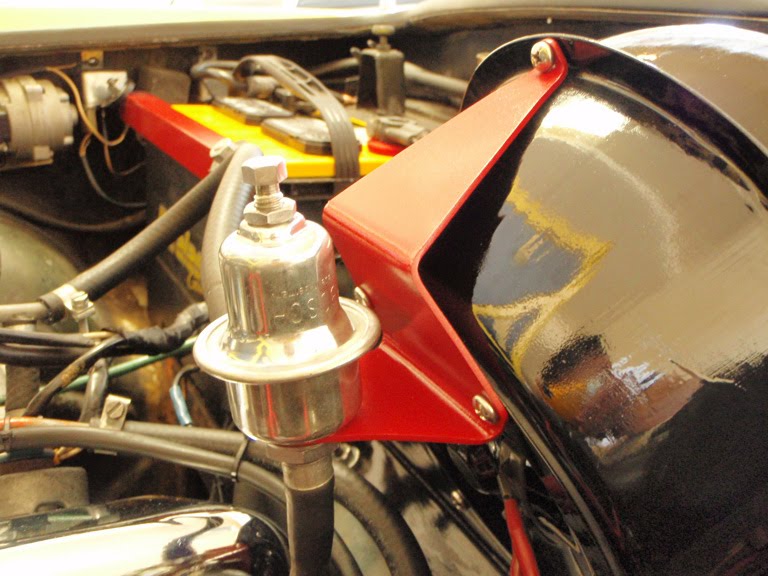
Fuel pressure regulator shown below was restored using a polishing wheel attachment on the Dremel rotary tool and Mothers Billet Metal Polish.

Before: Volvo 1800E Fuel Pressure Regulator - Before After: Volvo 1800E Fuel Pressure Regulator - After

Mounting bracket for fuel pressure regulator:

Before: Mounting Bracket - Before During: Mounting Bracket - During
After: Mounting Bracket - After Mothers Billet Metal Polish: Mothers Billet Metal Polish

The following photos are of the engine bay when I first got the Volvo compared to what it looks like to date:

Before: Volvo 1800E Engine Bay - Before After: Volvo 1800E Engine Bay - After
Volvo 1800E Engine Bay - BeforeVolvo 1800E Engine Bay - After

Saturday, February 27, 2010

PerTronix Ignitor Points-to-Electronic Ignition Conversion - Part 2

I was all ready to perfrom static timing on the engine this morning per the instructions on the "Swedish Enbassy" website when on a whim, I decided to turn the distributor clockwise about 5 degrees just to see what happens. Well ... I lucked-out! I had 50/50 odds of getting it back to its original timing prior to the PerTronix install by turning the distributor clockwise or counter-clockwise. The Volvo roared back to life sounding livelier and "younger" than it ever did as opposed to "tired & grumpy old Volvo." Well, that excitement lasted for several minutes until the engine warmed-up and it was back to a degrading idle and eventually stalling. The good news is, the PerTronix seems to be a promising upgrade ... all I need to do now is solve the warm engine stalling problem.

Having ruled out points as the possible culprit by replacing them with an electronic ignition module, it's time to look elsewhere for a fix. Let's see, so far the following checks have been conducted:

  • Replaced ignition coil
  • Replaced ignition wires
  • Replaced spark plugs
  • Replaced coolant/engine temperature sensor
  • Replaced engine thermostat
  • Cleaned all wiring terminals + grounds
  • Checked cold start valve - no leaks
  • MAPs sensor OK - unhooked the hose to the manifold and sucked on it. Tounge got stuck, so no leaks + pressure held. Resistance checks on terminals also OK.
  • Auxilary Air Valve (AAV) OK - Crimping the top hose dropped the idle when running engine cold. No effect on idle when running engine warm.
  • Air filter OK
  • Replaced points with PerTronix

Next on my list was to check for vacuum leaks and verify that the wiring harness to the Electronic Control Unit (ECU) was ok. While performing a visual check for any possible source of vacuum leaks, I did find a couple of tiny holes in the air intake hose pictured below. Since this hose is north of the intake manifold I don't think it has any effect on the vaccum. I sealed up the holes anyway with a few drops of Gorrilla Glue just for good measure and to prevent unfiltered air from entering the system.

Air Intake Hose: Volvo 1800E Air Intake Hose Holes in Air Intake Hose: Holes in Air Intake Hose

Now that the engine was equipped with a brand new coolant/engine temperature sensor, I wanted to verify that the wiring itself was in good shape, and thus not sending mixed signals to the ECU. I proceeded then to disconnect the Fuel Injection wiring harness from the ECU to perform the electrical checks outlined in this document I found in the Tech Archive of the VClassics Interactive website.

Couple of things I learned from this procedure: Plastic cover for the ECU slides off - do not pry it off like you would a can of paint (see photo below). Referencing the second photo below, pin #1 is on the right (where the red arrow is pointing), or furthest from the bunch of wires enternig the connector. Bottom line is, every single connection was good ... which is fantastic news since I wasn't looking forward to performing surgery on the wiring harness anyways!

ECU Cover Removal: Volvo 1800E ECU Cover Removal ECU Wiring Harness Connector: Volvo 1800E ECU Wiring Harness Connector

Sunday, February 21, 2010

PerTronix Ignitor Points-to-Electronic Ignition Conversion - Part 1

Alright ... same problem, different day. Engine starts & idles fine. Once warmed-up, it idles rough and eventually stalls. I've replaced the spark plugs, ignition wires, installed new thermostat and coolant temperature sensor in the engine block - no difference. The good news is there's only a finite number of possible causes and I've made a list of things to systematically check - it's only in the low hundreds. Among the items on my list are cold start valve leaks, vacuum leaks, MAPS sensor, fuel pressure, etc. There's also some suggestion on the forums that the gap on the breaker points may be closing down. Thus, being the last item on my list, and knowing my luck - it usually is the last thing that I'd check that's the culprit, I decided to skip all the other checks on my list for now and head straight for the last item on the list in an attempt to alter destiny.

Since I was already planning to perform a points-to-electronic ignition conversion and already have the PerTronix Ignitor module on hand, I decided to perform the upgrade which would eliminate the points & condensor ignition altogether, and hence any problems attributed to faulty points. Having spent a considerable amount of time on the forums trolling for installation notes specific to the Volvo 1800E with current sensing tachnometers, I was able to piece together shards of information into the following 2 wiring diagrams drawn up by my 3 year old daughter using crayons. Ok ... so I did do the drawings myself. The diagram on the left is how the stock wiring should look like for 1800E models. The one on the right is how the PerTronix module needs to be wired to get the current sensing tachnometer to work. My car does not have a ballast resistor going to the coil, so this implementation is specific to my set-up. Really simple - red PerTronix wire goes to ignition coil positive. Black PerTronix wire connects to white tach wire (or faded white on 40 year old cars!). The red PerTronix wire was not long enough to reach the coil on my car, and the black wire was way longer that it needed to be for my set-up, so I trimmed the black wire down and used the remains to lengthen the red wire for my specific application.

Stock Wiring diagram: Volvo 1800E Stock Ignition Wiring PerTronix Wiring Diagram: Volvo 1800E PerTronix Ignitor Wiring

The PerTronix installation walks you through removing the distributor cap, rotor, and points, followed by the installation of the module, and finally threading the wires through the distributor housing. Fuhgettaboutit! Save yourself the trouble - after removing the rotor and points, thread the wires through first before installing the module! Pictured below is the problematic somebitch! Attempting to thread the rubber grommet from the Pertronix module through the tiny hole (left by removing the condensor wire) from the inside of the distributor is an exercise you don't want to go through! If you follow PerTronix's instructions and install the module first before threading the wires and rubber grommet through, you'll find that there's not enough wiggle room to work the thing. In addition, the terminals on the PerTronix wires has barely enough room to clear the hole in the distributor housing. Not impossible - it's just a tight fit. Best to deal with it first before installing the module.

Problematic Somebitch: PerTronix Ignitor Electronic Ignition Module Wire Terminal Thru Distributor Housing: PerTronix Ignitor Wire Terminal

Here's how I did it: Remove the rubber donut completely. Thread it off the PerTronix wires and set it aside, but leave the coned-shaped other half attached to the wires. Next, thread the wires through the distributor housing (from the inside of the distributor of course). Apply dielectric grease all over the rubber donut ... inside the donut hole, inner lip, etc. The dielectric grease is just there as a lubricant to get the donut into the hole ... you can wipe off the mess later. Finally, thread the donut back onto the wires and ease it into hole of the distributor housing. I find that it's much easier to work with the rubber donut from the outside of the distributor. Apply pressure with thumb while slowly rotating the donut to get it to slip into the hole. Once inserted, thread the rest of the wires and the coned-shaped grommet through the hole in the donut to form a tight seal. You're done - follow the rest of the PerTronix manual to complete the rest of the installation.

Installing PerTronix Rubber Grommet: Installing PerTronix Rubber Grommet PerTronix Rubber Grommet Installed: PerTronix Rubber Grommet Installed

Although I do realize that it is necessary to reset the timing after the PerTronix installation as the triggering points are different for points vs. electronic module, I was hoping that the "old" timing would be "close enough". That way (assuming that this upgrade took care of the stalling problem), I would be able to drive to my mechanic and have the professionals adjust the timing with their fancy equipment. Boy, was I wrong! Timing was way off! The engine would barely stay running. Everything else worked fine - starts fine, and the tachometer works, indicating that the install was correct. All that is needed now is to adjust the timing .. which I'll save for next week's challenge.

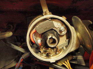
Before: Volvo 1800E Stock Points & Condensor Ignition After: PerTronix Module Installed

I found an article on static timing a B20 engine on the Swedish Embassy website, which should prove useful for next week's challenge. I tried reading it briefly, but I think I broke a couple of my teeth in the process. I'll have to give it a thorough read this weekend ... right after I figure out what's TDC, what's 16 degrees BTC, what's a crankshaft, what's a timing cover, and what do timing marks look like or where to find them.

Saturday, January 16, 2010

PerTronix Flame-Thrower & MSD Wires Installed!

Lots and lots of dielectric grease is what you'll need for building custom spark plug wire sets! The boots are almost impossible to thread through unless they're lubricated with a generous amount of dielectric grease. The spark plugs I ordered didn't show up for this weekend's party (they're on backorder), so I still can't tell if any of these replacements will solve the "no start" problem. The plugs that I currently have in the engine have the old school styled terminals which do not fit the plug terminals on the new wires. Besides, the old spark plugs looked pretty fouled, so I hope that's the extent of my problem. Here's the before-and-after photos of the wire upgrade. I'm still not sure how I feel about the new wire set. I like the look of the red wires, but at this point I much prefer the cleaner look of the stock boots on both the spark plug and the distributor end. The grey colored oversized MSD boots might take a while getting used to, however they are built that way to take a pounding from the engine heat and oils. BTW - These wires really do have low resistance! I checked them with a multi-meter and they really do only produce 40 - 50 ohms of resistance per foot, which translates to greater efficiency in the transfer of energy to the spark plugs.

Stock Spark Plug Wires: Volvo P1800 Spark Plug Wires - Before MSD 8.5mm Super Conductors: Volvo P1800 Spark Plug Wires - After

I also replaced the stock Bosch ignition coil with the PerTronix Flame-Thrower coil which adds another chrome element in the "looks" department of the engine bay. The photo below shows the new coil with new red coil wire that I built using the same MSD 8.5mm wire kit used to build the spark plug wires.

Stock Ignition Coil: QEM Bosch Ignition Coil PerTronix Flame-Thrower Coil: PerTronix Flame-Thrower Coil

Friday, January 15, 2010

Diode Wire Kit Has Arrived

The Diode Wire Kit from IPD has arrived. Unfortunately, it's not something that I'll need for my application. This kit is used to bypass the original single terminal ignition coil without having to cut into the armored cable for the ignition switch for P1800's up to 1968 (yes, I now know what the "armored cable" is). The PerTronix Flame-Thrower coil that I purchased has the conventional dual terminals, hence no need for this bypass. Here's a picture of the kit anyways before I send it back. It does come with detailed instructions on how to perform the surgery.

Wednesday, January 13, 2010

Ignition Components Have Arrived!

The MSD 8.5mm Super Conductor spark plug wire set, PerTronix Ignitor points-to-electronic ignition conversion kit, and PerTronix Flame-Thrower ignition coil I ordered have arrived! The spark plug wire set came with the terminals and the boots already installed on the spark plug end. The distributor end of the wires are left bare so that the wires may be cut to the appropriate length and attached to the included socket or HEI-style boots. To my surprise, the kit also included a coil wire! I wish they would include this juicy fact in their product description ... it would have saved me the trouble of buying that additional coil wire. Also included in the kit is a mini wire stripper/crimper to build the cables. Heads-up: you'll need a vise to complete the installation.

Pictured below right is the sexy looking PerTronix ignition coil that'll spit out 40,000 electronic frying volts! First thing that needs to go is the sticker. I regret ordering a chrome bracket for the coil. Chrome-on-chrome might be overkill. I wonder if they make a coil bracket in black ... or red? All I need now are for the spark plugs to show up before the weekend.

MSD Super Conductor Spark Plug Wires: MSD 8.5mm Super Conductor Spark Plug Wire Set PerTronix Ignitor & Flame-Thrower Coil: Volvo P1800 PerTronix Ignitor & Flame-Thrower Ignition Coil

Sunday, January 10, 2010

Oh Oh, Trouble!!!

The engine fired up again on the first try. Idle is still rough and erratic. I didn't drive it this time - just left it idling in the garage to see what happens. Once things started to warm up, I gave it some gas to rev it up and as usual, once my foot was off the gas pedal, the engine idled low and eventually stalled. This time it's completely dead! Each subsequent try resulted in a weaker crank until there was no play at all (after about 3 attempted starts). Where's the love? I don't think it's the thermostat anymore although I'm not ruling that out yet. This sounds like a whole new problem and I'm not going to try cranking up the engine again at the risk of frying my starter. This new developments has forced me to expedite the ignition system upgrade that I had planned anyways. There are so many things that could cause a "no start" scenario, I think I'll start by ruling out the ignition system by performing the following upgrades:

  • Upgrade spark plugs
  • Upgrade spark plug wires & coil wire
  • Upgrade ignition coil
  • Perform a points-to-electronic ignition conversion

A quick check on the battery with a multi-meter quickly ruled out lack of power as the culprit as the battery has a full 12 volts. Fouled plugs can easily contribute to idling or "no start" problems. A quick check on my plugs I discovered, was neither quick nor easy! None of my standard spark plug sockets would fit, nor would any of my long reach sockets for the matter! It turns out, the plugs on the Volvo P1800 are 13/16 hex - that's bloody big! Why so large? Me thinks it's because the B20 engine (and it's predeccesor, the B18) was developed by taking Volvo's V8 truck engine and slicing it in half to produce a straight-4 to fit in a car. No wonder the engine is bullet proof - that and it was made for the freezing cold Swedish climate. In any case, it turned out to be an exercise to track down the appropriately sized plug socket and the replacement spark plugs as none of the neighborhood auto stores carried them.

I ended up ordering all the upgrades online from various sources and am now waiting for the parts to arrive, hopefully in time for the weekend. I got the NGK standard spark plugs (Part No. BP7HS) and a chrome ignition coil bracket from JEGS. I decided on wires by MSD Ignition: I'll be building my own custom spark plug wires using the MSD 8.5mm Super Conductor Spark Plug Wire Set (part no. 31159) and coil wire is MSD's 8.5mm Replacement Coil Wire (part no. 84049). I decided on these as they're red, and have the lowest resistance without electronic interference. They do cost twice as much though, but I'd rather do it once right and never deal with it again.

I also bought the PerTronix Ignitor electronic ignition system and the PerTronix Flame-Thrower Coil because they're a popular upgrade from points-type ignition systems amongst classic Volvo enthusiasts, therefore there's lots of support available if things go wrong ... and they have the ignition coil in chrome! The Flame-Thrower Coil has a 40,000V rating which is a substantially higher output potential than an OEM coil - sounds like it'll light a pretty big fire ... must be good, right?!! As for the PerTronix Ignitor, their sales literature states "never adjust or change points again". I don't even know what points are, but the fact that I don't have to mess with them got me sold - hey, one less thing to worry about right?!! Here's a Volvo specific application chart from Retro Rockets, a distributor of PerTronix Ignition Systems. All these components can be purchased directly from the manufacturer's websites, but I got mine from a much cheaper source at Summit Racing Equipment.

The PerTronix Ignitor points-to-electronic conversion seems like a simple enough install that even I can't screw-up, but it does involve resetting the timing and adjusting the idle which is way over my head, so this is one upgrade that I'll have my mechanic perform for me as part of the much needed tune-up. Now, all I have to do is find a mechanic ... and get the Volvo working so that I can drive it to the shop without stalling out and leaving me stranded. To make life easier for the mechanic, I also forked out $10 for a custom Diode Wire Kit from IPD that is used to "bypass the original armored coil without having to cut into the armored cable". Once again, I don't know what an "armored coil" is, but the "no cutting into" sounds like a darn good idea.

In summary, phase 1 is to get the engine firing. Phase 2 is to get it to purr like a kitten. At the rate that everything is shutting down, hopefully I'll be able to fix the problem before it causes a chain reaction leading to a complete catastrophic failure. On second thought - the car is already stalled-out in the garage, so it can't get any worse that that. Yay - good times! Somebody quick ... scissor kick me in the back of the head!

Sunday, December 13, 2009

Engine Bay - Red & Chrome!

I took it easy this weekend. No major overhaul, just slowly reinstalling components that have been worked on the weeks before back into the engine bay. In order to get the heater back into the car, everything else that I removed has to be reinstalled in reverse order, starting with the repainted radiator fan and the chromed fan-belt pulley. The newly polished water outlet pipe was also reattached to the engine block.

Radiator Fan + Pulley - Before: Radiator Fan + Pulley - Before Radiator Fan + Pulley - After: Radiator Fan + Pulley - After
Radiator Fan + Water Outlet Pipe - Before: Radiator Fan + Water Outlet Pipe - Before Radiator Fan + Water Outlet Pipe - After: Radiator Fan + Water Outlet Pipe - After

Here's the front view of the red radiator fan and a bird's eye view of the engine compartment showing the freshly painted battery support arm.

Repainted Radiator Fan: Repainted Radiator Fan - Front View Reinstalled Battery Support Arm: Reinstalled Battery Support Arm

Saturday, December 5, 2009

New Colors

I've got lots of photos to share after spending the entire weekend with a facemask on and a couple of aerosol cans of paint. The first series of photos below are of the air duct which directs fresh air to the heater unit. The color scheme that I've picked for the engine compartment is black, cast iron grey, silver (or light gray), red, with some chrome highlights. The first photo below shows the air duct in its original black color. The second photo shows bare metal after sandblasting. The third is after 2 coats of POR-15 rust preventative paint followed by 3 coats of their tie-coat primer wet sanded down to a smooth finish. The fourth photo is of the finished air duct spray painted in cast iron grey.

Air Duct in Original Condition: Air Duct - Original Condition Air Duct After Sandblasting: Air Duct - After Sandblasting
Air Duct With POR-15 + Primer: Air Duct - After Primer Air Duct With Final Color: Air Duct - Final Color

The following series of photos are before-and-after shots of the radiator fan and the support arm for the battery. They've both been sandblasted to remove any rust and old paint, coated with POR-15 rust preventative paint, and coated with primer before the final application of red paint. I think the red accents against the black, silver, and cast iron grey of the other components in the engine compartment will add some dimension to the overall pallette. I call this the "Peacekeeper Color Scheme" from the farscape television series ... it's a sci-fi thing ... nevermind! I'm sure some P1800 purists will be screaming bloody murder because I changed the original color of some of the components - they can call me on this toll-free number to "express" themselves: 1-800-EAT-SHIT. Operators are standing by.

Radiator Fan - Before: Radiator Fan - Before Radiator Fan - After: Radiator Fan - After
Battery Support Arm - Before: Battery Support Arm - Before Battery Support Arm - After: Battery Support Arm - After

This final series of photos depict the process of getting one of these components from its initial banged-up condition to the final painted stage. Pictured below is the mount for the coolant overflow bottle. I meant for this to be painted in POR-15 silver initially and left as is without any top-coat because it won't be seen once the coolant overflow bottle is reattached, but as luck would have it, the silver POR-15 dried up in the can, so I had to work with black instead and top-coat with cast iron grey. After sandblasting to remove the rust, 2 coats of POR-15 were applied (2 hours between coats) followed by 2 coats of their tie-coat primer (which I would never buy again). The first coat of primer was applied 4 hours after the final coat of POR-15, when it was dry to the touch, but tacky with a slight finger drag. I found through experimentation that this is the only way to get that 1st coat of primer to adhere. The 2nd coat of primer was applied 12 hours later (after the 1st coat dried). After yet another 12 hours of curing, the primer was wet-sanded down to a smooth finish. All of this was done days or weeks prior to this weekend's paint job of course, as there is a lot of "down time" involved waiting for stuff to dry and only being able to do one side at the time for most components. The spray painting process is fairly simple. I like to start with 2 very light coats of paint with 10 minutes between each coat. 10 minutes after the 2nd light coat, I then blast it with a medium-wet coat of paint to get that smooth shiny finish.

Coolant Overflow Bottle Mount - Before: Coolant Overflow Bottle Mount - Original Condition After Sandblasting, POR-15 & Primer: Coolant Overflow Bottle Mount - With Primer
With 2 Light Coats of Paint: Coolant Overflow Bottle Mount - 2 Light Coats of Paint Final Coat of Paint: Coolant Overflow Bottle Mount - Final Coat of Paint

Saturday, November 21, 2009

Chrome!

I just got back some pieces from the electro-plating shop. Since I have the radiator out and a clear shot at the fan and pulley system, I decided to yank those out to have the fan re-painted and the fan-belt pulley chromed. Pictured below clockwise from top is the water outlet pipe from the engine to the radiator, spacer between the fan and the pulley, and the fan-belt pulley. Both the water outlet pipe and the spacer are made of aluminium, and therefore cannot be chrome plated. The shop polished them the best they could instead. The fan-belt pulley however ended up with 4 layers of plating: 2 layers of copper, followed by nickel, and finally chromium. This thing looks like a piece of jewelry now ... I'm considering not putting it back on the engine and wearing it around my neck instead! The cowl intake grille is another piece that is made of aluminium, but the polishing process rendered it looking as good as chrome anyway. All of these were done for $60 - Not bad Kimosabe ... not bad.

Engine Components - Before: Engine Components - Before Engine Components - After: Engine Components - After
Cowl Intake Grille - Before: Cowl Intake Grille - Before Cowl Intake Grille - After: owl Intake Grille - After