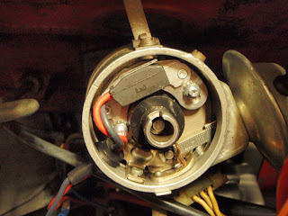
Alright ... same problem, different day. Engine starts & idles fine. Once warmed-up, it idles rough and eventually stalls. I've replaced the spark plugs, ignition wires, installed new thermostat and coolant temperature sensor in the engine block - no difference. The good news is there's only a finite number of possible causes and I've made a list of things to systematically check - it's only in the low hundreds. Among the items on my list are cold start valve leaks, vacuum leaks, MAPS sensor, fuel pressure, etc. There's also some suggestion on the forums that the gap on the breaker points may be closing down. Thus, being the last item on my list, and knowing my luck - it usually is the last thing that I'd check that's the culprit, I decided to skip all the other checks on my list for now and head straight for the last item on the list in an attempt to alter destiny.
Since I was already planning to perform a points-to-electronic ignition conversion and already have the PerTronix Ignitor module on hand, I decided to perform the upgrade which would eliminate the points & condensor ignition altogether, and hence any problems attributed to faulty points. Having spent a considerable amount of time on the forums trolling for installation notes specific to the Volvo 1800E with current sensing tachnometers, I was able to piece together shards of information into the following 2 wiring diagrams drawn up by my 3 year old daughter using crayons. Ok ... so I did do the drawings myself. The diagram on the left is how the stock wiring should look like for 1800E models. The one on the right is how the PerTronix module needs to be wired to get the current sensing tachnometer to work. My car does not have a ballast resistor going to the coil, so this implementation is specific to my set-up. Really simple - red PerTronix wire goes to ignition coil positive. Black PerTronix wire connects to white tach wire (or faded white on 40 year old cars!). The red PerTronix wire was not long enough to reach the coil on my car, and the black wire was way longer that it needed to be for my set-up, so I trimmed the black wire down and used the remains to lengthen the red wire for my specific application.
Stock Wiring diagram:

| PerTronix Wiring Diagram:

|
The PerTronix installation walks you through removing the distributor cap, rotor, and points, followed by the installation of the module, and finally threading the wires through the distributor housing. Fuhgettaboutit! Save yourself the trouble - after removing the rotor and points, thread the wires through first before installing the module! Pictured below is the problematic somebitch! Attempting to thread the rubber grommet from the Pertronix module through the tiny hole (left by removing the condensor wire) from the inside of the distributor is an exercise you don't want to go through! If you follow PerTronix's instructions and install the module first before threading the wires and rubber grommet through, you'll find that there's not enough wiggle room to work the thing. In addition, the terminals on the PerTronix wires has barely enough room to clear the hole in the distributor housing. Not impossible - it's just a tight fit. Best to deal with it first before installing the module.
Problematic Somebitch:

| Wire Terminal Thru Distributor Housing:

|
Here's how I did it: Remove the rubber donut completely. Thread it off the PerTronix wires and set it aside, but leave the coned-shaped other half attached to the wires. Next, thread the wires through the distributor housing (from the inside of the distributor of course). Apply dielectric grease all over the rubber donut ... inside the donut hole, inner lip, etc. The dielectric grease is just there as a lubricant to get the donut into the hole ... you can wipe off the mess later. Finally, thread the donut back onto the wires and ease it into hole of the distributor housing. I find that it's much easier to work with the rubber donut from the outside of the distributor. Apply pressure with thumb while slowly rotating the donut to get it to slip into the hole. Once inserted, thread the rest of the wires and the coned-shaped grommet through the hole in the donut to form a tight seal. You're done - follow the rest of the PerTronix manual to complete the rest of the installation.
Installing PerTronix Rubber Grommet:

| PerTronix Rubber Grommet Installed:

|
Although I do realize that it is necessary to reset the timing after the PerTronix installation as the triggering points are different for points vs. electronic module, I was hoping that the "old" timing would be "close enough". That way (assuming that this upgrade took care of the stalling problem), I would be able to drive to my mechanic and have the professionals adjust the timing with their fancy equipment. Boy, was I wrong! Timing was way off! The engine would barely stay running. Everything else worked fine - starts fine, and the tachometer works, indicating that the install was correct. All that is needed now is to adjust the timing .. which I'll save for next week's challenge.
Before:

| After:

|
I found an article on static timing a B20 engine on the Swedish Embassy website, which should prove useful for next week's challenge. I tried reading it briefly, but I think I broke a couple of my teeth in the process. I'll have to give it a thorough read this weekend ... right after I figure out what's TDC, what's 16 degrees BTC, what's a crankshaft, what's a timing cover, and what do timing marks look like or where to find them.


No comments:
Post a Comment