As mentioned in last week's post, the goal this weekend is to dial in the timing one notch better by performing static timing as outlined in this article on the Swedish Embassy website. Once this prerequisite procedure is done, my hope is to be able to mess with some variables that affect the air/fuel mixture to get the engine to stop stalling at 7 minutes so that I may drive it to the shop to have them fine tune everything. It took me awhile to get comfortable with attempting this procedure as I was getting confused comparing the Swedish Embassy article vs. the procedure outlined in my Owners Workshop Manual. It was really the instructions in my manual that was throwing me off. In particular, their scripture read (not verbatim, as I don't have it with me as I write this) "... turn the engine until the timing mark lines up with the "0" scale on the crank pulley ... back it off until the timing mark is opposite the 10 degree scale." The word "opposite" was throwing me off - I kept thinking 180 degrees from the 10 degree scale ... which is opposite right?!! No ... they should have been consistent with their verbiage and used "lines up" or "adjacent" instead!
Anyway, the main reason for this post is so that I could post some photos as a visual reference for myself in case I wake-up from a coma with minimal recollection and I have to do this again in the future. Note to self: this pictorial guide is to supplement the static timing instructions in the Swedish Embassy article ... Why? Because I'm a moron!
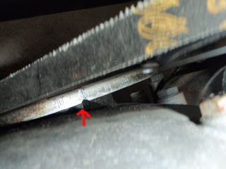
First photo below shows the 10 degree timing mark on the rim of the crank pulley lined-up with the pointer on the timing cover of the engine - this is 10 degrees BTDC (TDC is at "0"). The pointer is more like a fin (red arrow in photo). Timing marks are the numbers on the rim of the crank pulley (20 ... 10 ... 0 ... 10). It took a while to find the timing marks on the crank pulley the first time around as they were all covered up in grease. Rotation of engine is clockwise when looked at from the front. Second photo shows both valves for cylinder no. 1 up and closed at ignition point (TDC) as seen through removed oil filler cap. Top of cylinder should also be visible through spark plug hole no. 1 (that's the first one from the front of the engine).
Timing Marks on Engine:

| Valves For No. 1 Cylinder:

|
Third photo below shows orientation of distributor rotor at TDC. Rotor should be pointing to cylinder no. 1. Last photo is of spark plug no. 1 grounded to the valve cover. In summary, it all went well. I static timed it to 10 degrees BTDC, and the engine started right up. Now I can make adjustments to the throttle valve, throttle switch, and idle to see if I can get to the bottom of this stalling problem.
Distributor Rotor Orientation:

| Spark Plug on Valve Cover:

|


No comments:
Post a Comment